
BRANCHES AND FEEDERS
Use our Applications to find ratings and sizing of all components and conductors in conformance with Standards (UL 508A inside the panel, NFPA 79 inside the machine, NEC outside the machine.
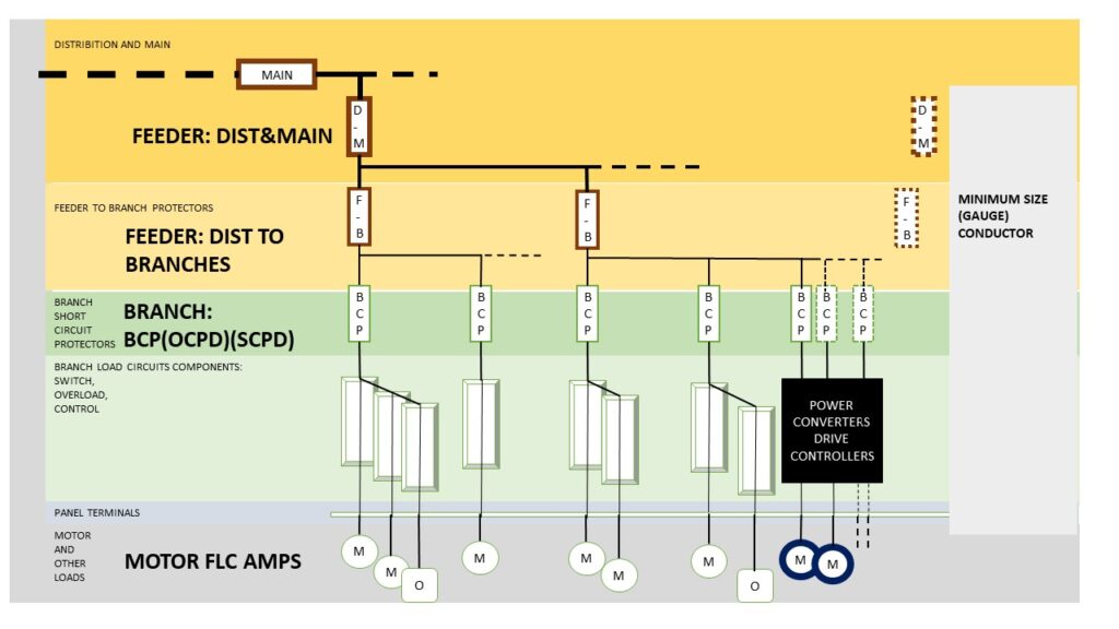
(Use CTRL + and CTRL – to zoom in and out)
24 VDC POWER EXAMPLE: OPTIMIZATION FOR CLEAN SIGNAL BASIS.
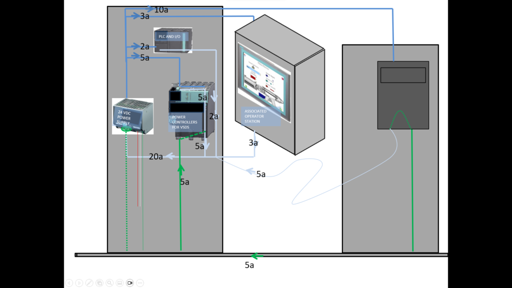
5 amps return through a random metal path. May cause significant shifts for signal voltage levels with respects to zero.
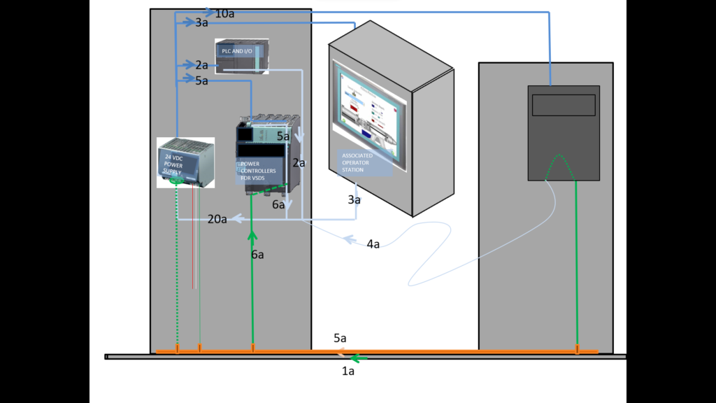
Ground copper bar becomes favored return path but still 1 amp randomly in metal. Potential shifts in signal level zero reference less.

Return wire size increased now is better return path available (taking 7 amps rather than 4 amps), but still 2 amps in the ground busbar and the 1 amp in the metal. Potential shifts in signal level zero reference also less.
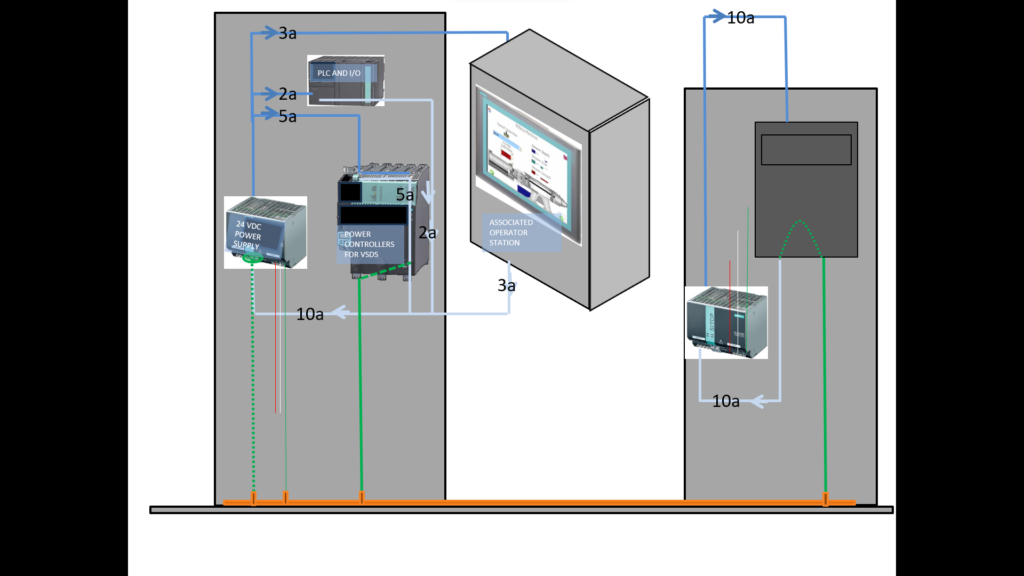
Another separate 24 vdc power supply is added in the adjacent location. All current there is returned there. No 24VDC current path is needed in the ground bar or metal and none flows in either. This would be the optimum solution.
MITIGATION OF ELECTRO MAGNETIC INTERFERENCE IN VARIABLE SPEED DRIVE SYSTEM:
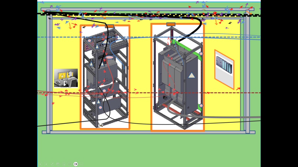
System is at rest. Control Power only is on (red wires). Running above are cables from other systems.
Drives are now running under load, two drives in the left cabinet, one larger on the right. Line cables from above (black), motor cables (black or grey) below, two from the left side cabinet, one (larger) from the right. Motor cables are not shielded.
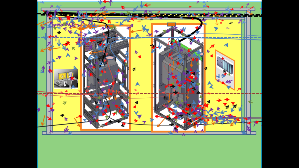
Same as previous except now the motor cables are shielded and properly terminated to ground at each end. Each end ground to be at equal potential and cable shields to use a clamp that covers their complete 360 degrees circumference. Note the concentration (not reduction) of the noise.
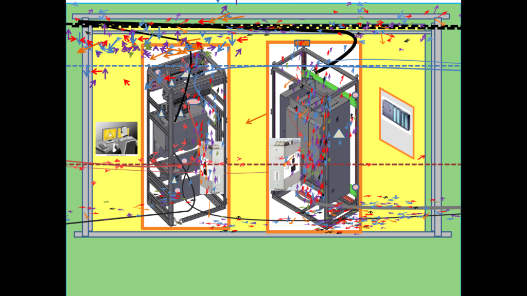
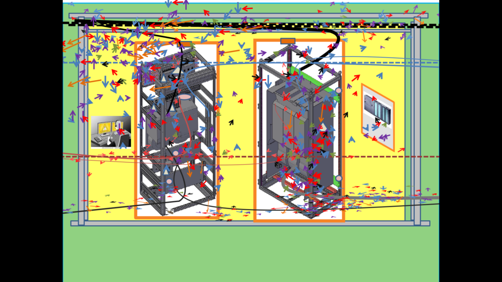
Filters are now added into each cabinet. These filters are tuned to the levels of noise, matched to the particular power controller. They act to draw the noise current through them and back to the source (rather than letting those currents find random ways back). Again this does not reduce the noise, it concentrates it to a path away from sensitive controls.
ZONING INSIDE A CABINET AS A MITIGATION MEASURE AGAINST PERFORMANCE DEGRADATION DUE TO ELECTRO MAGNETIC INTERFERENCE
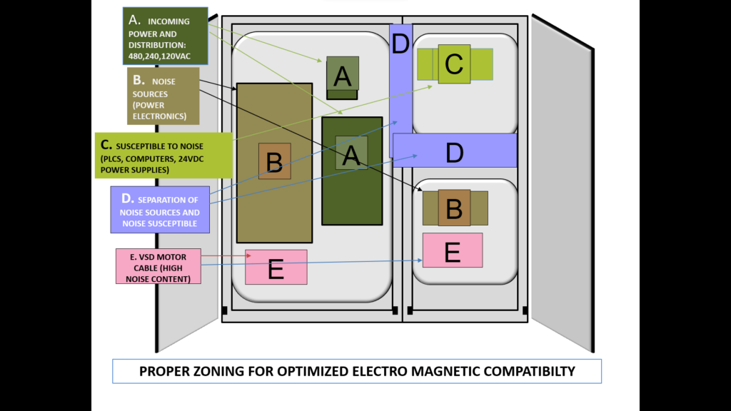
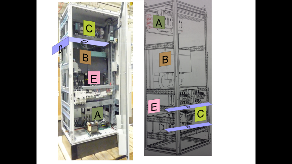
Note also the idea of not only height and width but also use of the depth as shown here.
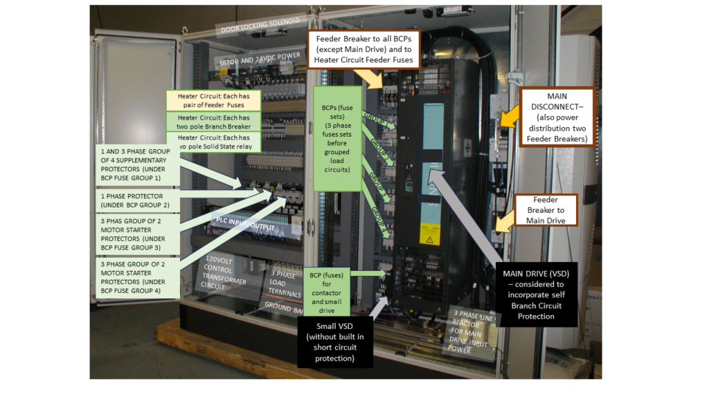
NAMEPLATE SCCR (SHORT CIRCUIT CURRENT RATING) OF AN INDUSTRIAL CONTROL PANEL.
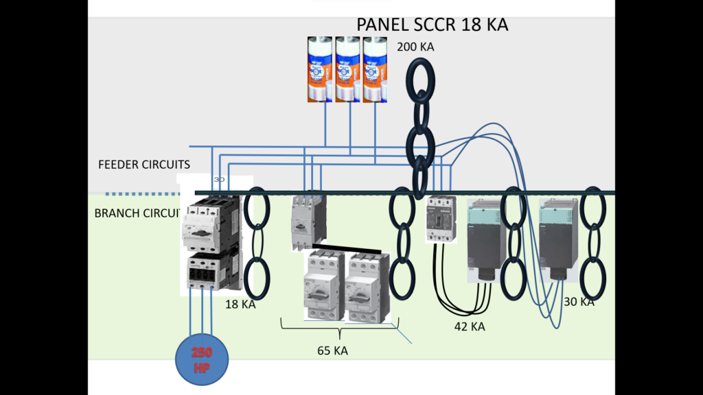
The idea of “weakest” link is illustrated. The overall panel SCCR rating is 18KA due to the branch on the left. The SCCRs of the feeder and branch components are shown. Some of those values are by virtue of the single component and may be marked on the component or on their data sheet, or as a group (containing components with low SCCRs by themselves but higher values when preceded by a short circuit protection component. In the latter case, manufactures should publish values for such combined higher SCCR values).
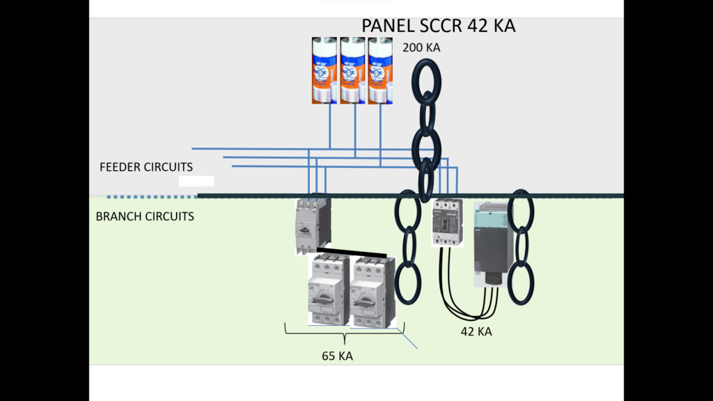
The overall panel SCCR rating is 42 KA. One method of raising SCCR is to move circuits or replace with better components or higher SCCR tested groups.
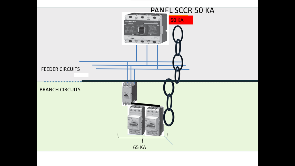
Here the feeder fuses have been replaced with a circuit breaker which has a SCCR rating of 50 KA, which, in the case shown, is the weakest link. The SCCR now to show on the panel nameplate is 50 KA.
Another Example:
Panel SCCR as shown?
Panel SCCR if Feeder Breaker is changed to 200 KA fuses set?
Panel SCCR if left side Branch SCCR is raised from 5 KA to 22 KA?
Panel SCCR if Busbar set is changed to a set designed/tested to 42 KA SCCR
Panel SCCR if Feeder Breaker is replaced with one with 50 KA SCCR rating.
5,5,10,42,42
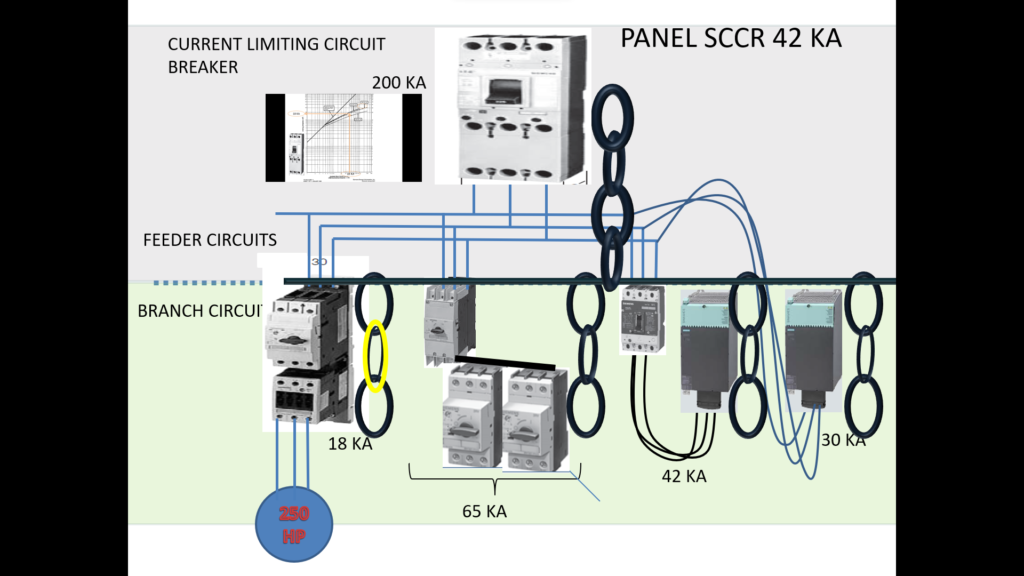
Example of raising the panel SCCR by current limiting in the feeder to several branches together. Here a panel SCCR level of 42 KA was required (perhaps requested by the user after an analysis of the plant supply system). Using the published characteristic for a particular breaker it is found that a fault level of 42 KA limits the peak let through fault to 18 KA. This then can be tolerated by the existing weakest link.
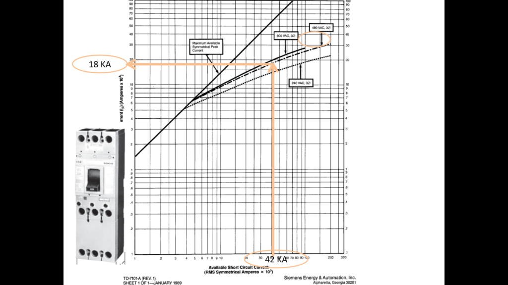
The characteristic of the current limiting breaker employed above.
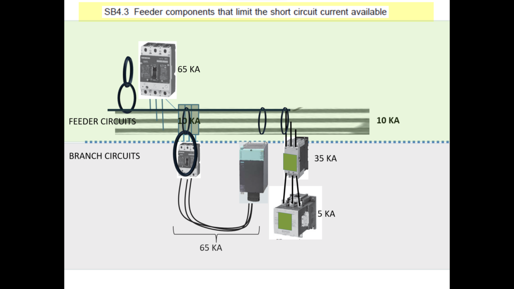
Here the panel SCCR is 5 KA. The contactor (bottom right) is rated only for 5KA (there is no information that tells us that the combination of it with the preceding breaker (35 KA by itself) leads to an combined higher SCCR for that branch.
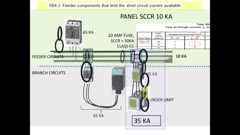
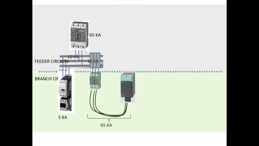
Example of raising the panel SCCR by current limiting in the feed to a particular branch: Here a set of fuses are added in the feeder. UL provide a table that can be used to determine the let through peak current of fuses by type in ranges of available short circuit current. In this case the required panel SCCR rating is to be under 50 KA. The table then tells us that the let through will be limited to no more than 3 KA. The 5 KA rated contactor would no longer be a weak link as it would never experience more than 3 KA for fault levels up to 50 KA. The whole panel SCCR rating would now be 10 KA, the busbar system now be the weakest.